
REVISED Audio Output Transformer Amplifier Circuit Diagram
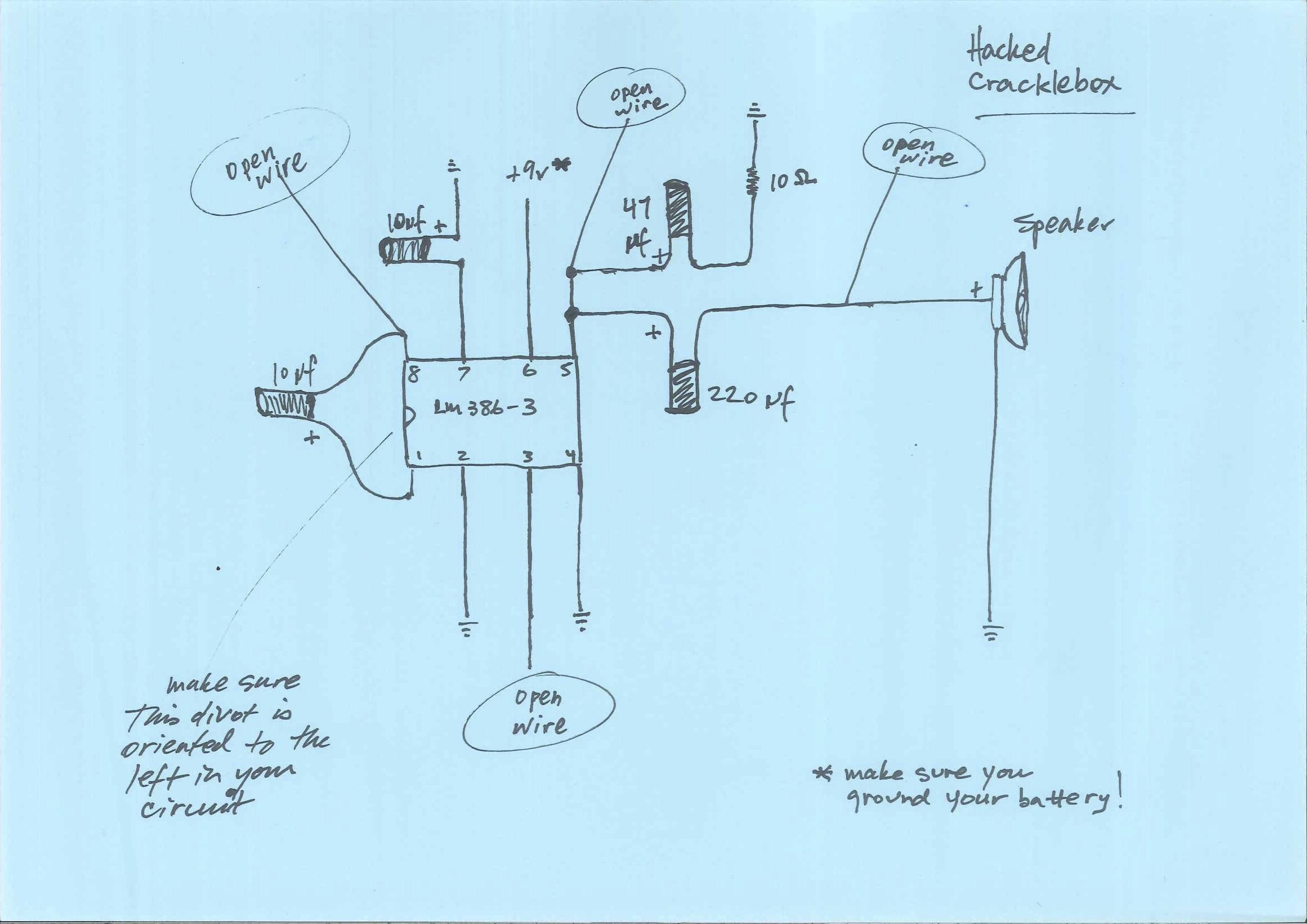
Hacked Cracklebox
CrackleboxSchematicFall2018_Final2
Please note: The 10 Ohm resistor coming off the 47uf cap on the top of the diagram should be a 100 Ohm resistor. I will fix the schematic as soon as I have time.
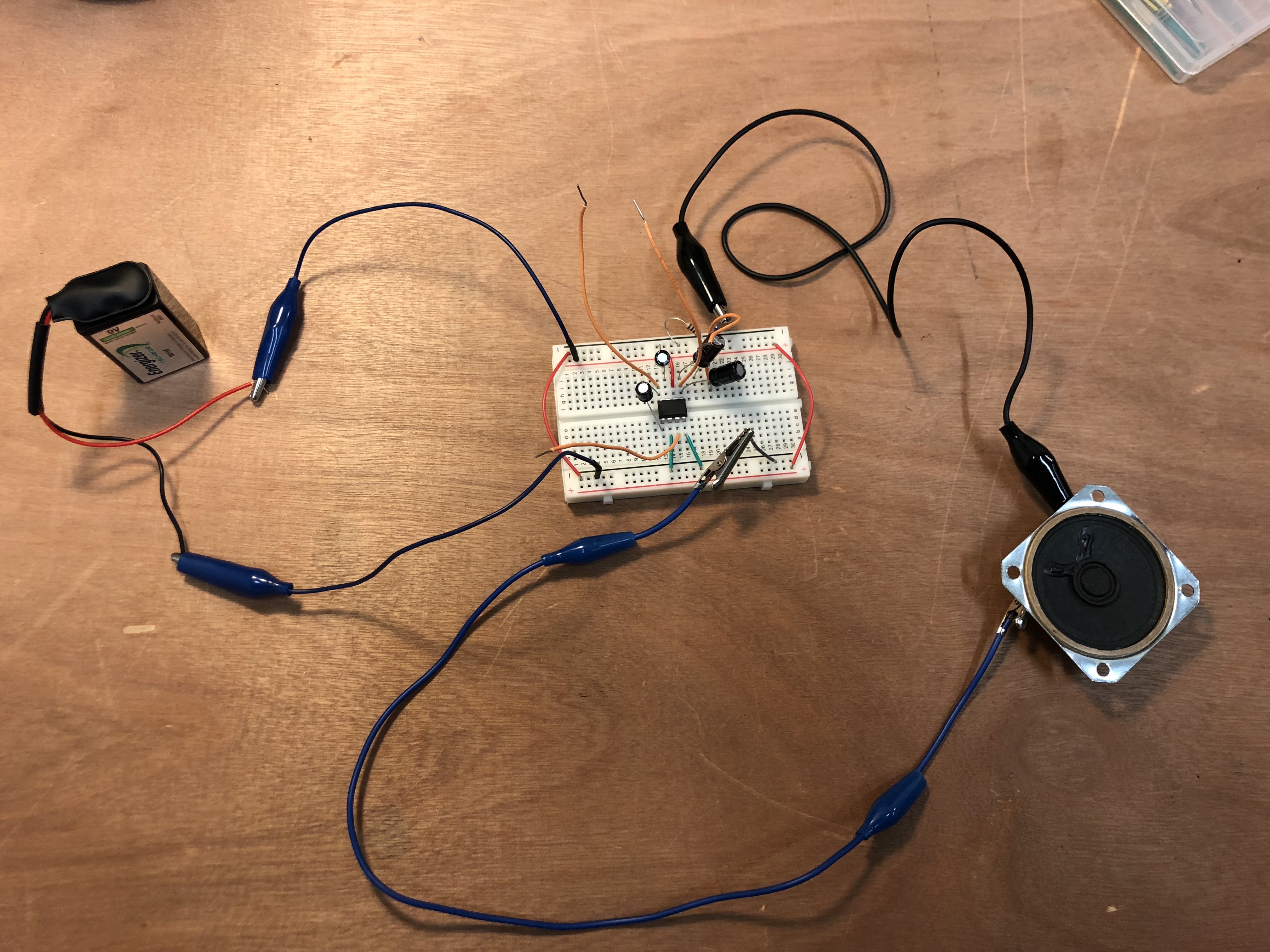
and this photo of the breadboarded circuit:
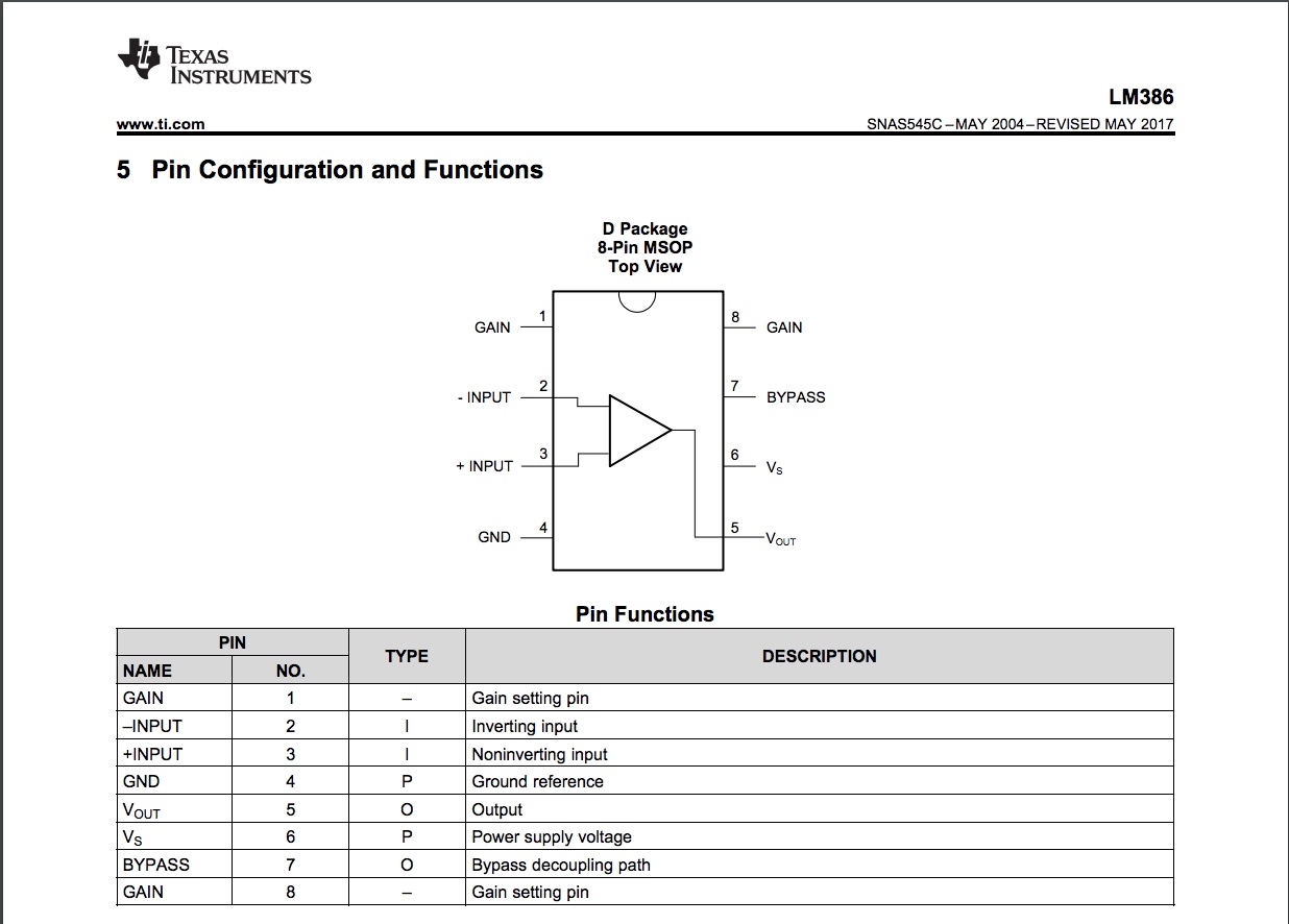
LM386-3 Pinout
 ——————————————————————————————————————–
Atari Punk Console

http://www.instructables.com/file/FRC55EBGVVPD18L/?size=LARGE
Some notes about the above schematic:
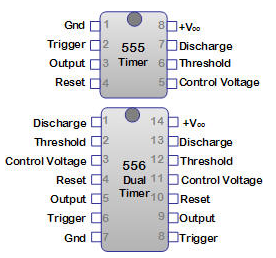
- Notice where the lines coming out of pins one and two cross the line coming from pin four. The line is curved at those points. This means it is NOT a connection. This happens on the other side of the diagram as well in several places.
- Also notice the connection between pin 5 and pin 8. This connects the output of one of the 555 timers (there are two 555’s in one 556) to the “trigger” of the other 555.
- Voltage (+) from your battery connects to pin 14.
- The signal output in this 556 circuit comes from pin 9.
- There are two potentiometers in this circuit (VR1 and VR2) that control frequency. The nose of the pot connects to voltage and one of the ears connects to the discharge pin (1 and 13) — it is the same on both sides of the circuit.
- For this build you should use a 1/4″ female jack as the output (top right of the diagram) NOT the speaker output (bottom right).
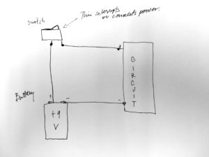
- If you are feeling wild, see below for ideas about how to add an on/off switch to your circuit, and /or how to add LEDs. It would be possible to add an LED to the signal output or as an on/off indicator. We will be talking more abou these components as we go along.
555/556 Pinout
HOW TO USE A BREADBOARD
https://learn.sparkfun.com/tutorials/how-to-use-a-breadboard
HOW TO READ A SCHEMATIC
https://learn.sparkfun.com/tutorials/how-to-read-a-schematic
HOW TO USE A MULTIMETER
https://learn.sparkfun.com/tutorials/how-to-use-a-multimeter
Illustrator Box template (this is a pdf, let me know if you want the .ai file for illustrator)
Kogawa’s FM transmitter diagram
http://anarchy.translocal.jp/radio/micro/simplestTX01.pdf
http://anarchy.translocal.jp/radio/micro/howtosolder/howtosolder.html
How to Build a DIY Analog Video Transmitter
http://crackedraytube.com/pdfs/building_a_diy_transmitter.pdf
Some Basic Switches
- Single Pole Double Throw (SPDT toggle)
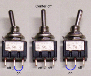
Use this type of switch to switch switch between two different outputs, or between two different and distinct “routes in your circuits.
2. Single Pole Single Throw (SPST toggle)
Use this type of switch as an on/off for your circuit.
And/or this:
3. More on how to wire common switches:
http://www.learningaboutelectronics.com/Articles/Toggle-switch-wiring.php
Also, see Nic Collins book Chapter 16 pp. 113-117.
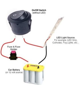
4. How to wire a 3-prong LED rocker switch
LED basics
https://learn.sparkfun.com/tutorials/light-emitting-diodes-leds
Also, see Nic’s chapter 21 for more on LEDs and photoresistors.
How to wire a volume knob:
https://www.wikihow.com/Wire-a-Potentiometer
Also, here is a link to the isometric paper that you can print out like the kind we used in class.
WorksheetWorks_IsometricGraphPaper_1